Flipping Back to Basics - Wiry Tetris
16 April 2016It's been exactly 23 months since I started writing this post. I packed everything up when I moved house have only just unpacked my electronics stuff. I can't remember all that I was going to put in those posts so I'll aim to pick things up again in further posts as I remember them.
TLDR
- The code: https://github.com/MattsGitCode/FlipDotTetris
- The video:
The unfinished symphony
Expanding on my last post about controlling a single dot I wanted to control all 240 of them. As I'm writing this post with the everlasting wisdom endowed by hindsight it will mostly be a success story. I discovered that the Farnell trade counter is but 5 minutes from my house and so I was able to pick up appropriate components as needed. Free coffee makes it a worthwhile visit.
Shift Driving Sinks
Last time I used 4 transistors, 2 to drive current to the row and column, and 2 to sink current from the row and column. These are known as discrete components, each transistor is packaged individually. Scaling this up to 30 rows and 8 columns would result in 76 transistors and a very messy and unmaintainable circuit. Integrated circuits can help to reduce the clutter here by packaging an array of transistors up into a single package, tying the common leads together into a single pin.
The source drivers I'm using are Micrel 2981's, they have 8 outputs but each one is a lot more than a single transistor. Here's the schematic for a single output.
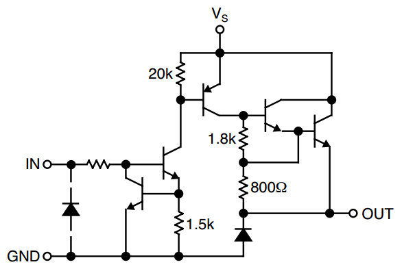
There are 8 of these in a package just 21mm long, which fascinates me even though I know there are much more densely packed components around. Unlike the discrete PNP transistors, which had to have the base (input) pulled low to allow current to flow, this circuitry means that taking the input high will enable current to flow. The integrated circuit takes the circuit from being analogue, with concerns about resistors and saturation points, to being digital, with concerns only about 1's and 0's. I like this, I can count to 1, I'm employed for my ability to do so.
The sink drivers are similar but with a few less components per pin, it's still taking an input high in order to enable the output and let current flow through it to ground. 8 outputs per package means I have to use 5 of each type, with a few outputs spare.
This takes care of the high current requirements of the display, I still have 76 inputs to address from the microcontroller. This is where those shift registers come into play that I mentioned a few posts ago. I found that I could use 3 outputs from the microcontroller to shift data into along a daisy-chain of these components to achieve as many outputs as required.
Toasted Chips
This worked, sometimes, I found that on occasion when powering it up nothing would happen but several of the driver chips would get a bit toasty. I'm not going to lie, I burnt myself a few times. Investigating the source of this problem I read in the datasheet that all unused inputs should be held high or low, rather than just floating, as the behaviour is otherwise undefined. My suspicion was that the outputs of some of the shift registers were enabled and causing short circuits between the drivers.
The shift registers have a pin to enable the output and connecting this to 5v, via a resistor, disables the outputs during power up. A fourth pin on the microcontroller can then be used to override this, pulling the output enable pin low, and enable the output of the shift registers.
Software
With Tetris being my end goal the display is going to be updating fairly regularly as pieces fall and rotate. I didn't want to be cycling through every dot each time to ensure it's in the correct state. This means only cycling through the dots that need to change state, which means keeping track of what the current state of each of them is. This is achieved by abstracting the hardware aspect, similar to a driver on a PC, and keeping track of the state within that. I have a Display class for this. The higher level application interacts with this by writing out its current display requirements into an instance of a Buffer class. The display then iterates through each dot in the buffer and compares it to its internal state. If it requires an update to the display it will make that change, otherwise it will move on to the next dot. Using this technique allows a fairly fast refresh rate of the display.
void Display::SetDisplay(const Buffer &buffer)
{
    for (uint8_t x = 0; x < 30; ++x)
    for (uint8_t y = 0; y < 8; ++y)
    {
        bool oldSet = frontBuffer.columns[x] & (1UL <<  y);
        bool newSet = buffer.columns[x] & (1UL <<  y);
        if (oldSet != newSet)
        {
            SetDot(x, y, newSet);
            frontBuffer.SetDot(x, y, newSet);
        }
    }
}