Flipping Back to Basics - Transistor Trickery
19 April 2014After working out in my last post that I wouldn't be able to control these dots directly from a microcontroller I'm going to take a look at the PCB that's connected to it.
Using the continuity checker on the multimeter I can map the 70 pins on the display panel connector:
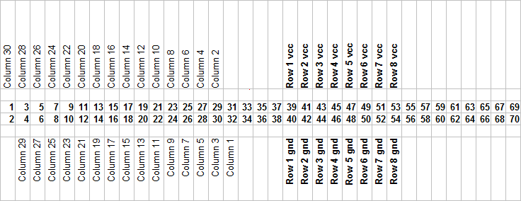
The right-most 16 pins don't seem to be connected to anything.
I can also map the relevant pin connections on the attached PCB:
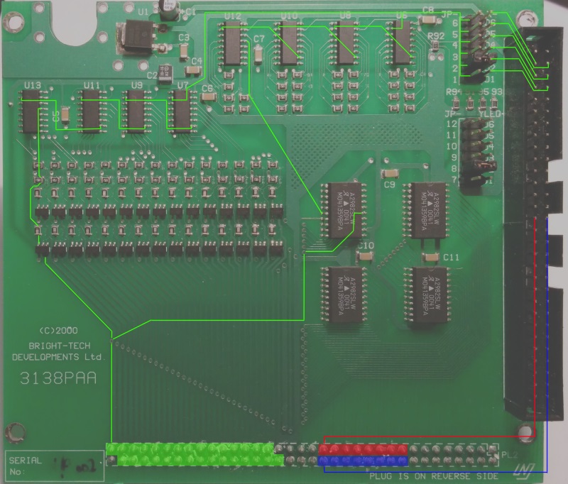
This looks like both the row positive and negative are managed on another separate board. The columns, however, are managed on this board. The 4 A2982SLW's on the right are the current source for the columns, meaning the 30 little 6-pin components on the left must provide some way to sink the current.
Both the current sources and sinks are switched from the shift registers at the top of the board. These shift registers are connected to one side of the 6 jumper pins at the top right. The jumper allows the main control board to address a column on any of the 3 display panels that make up the whole by sending the serial data over the correct pin.
Due to the rows being managed back on the main control board I can't interface purely with this board to control the dots. I'm going to change my approach slightly and build my own replacement to this board that will talk directly to the 70 pins on the display panel.
Transistors
A transistor, as I understand them, can be used to amplify current in a switch type manner. There are 2 types: NPN and PNP. NPN transistors are used to switch on the low voltage side of the load, whereas PNP transistors are used to switch on the high voltage side of the load. The load, in this case, will be the coil on each dot. I don't know why the 2 different types are used differently but I'm going to stick to this as it's what I've read.
They each have 3 connectors: emitter, base, and collector. When the base of an NPN transistor is connected to a positive voltage, it allows current to flow from the collector through to the emitter. Conversely, when the base of a PNP transistor is connected to ground, it allows current to flow from the emitter through to the collector.
With this in mind, the following circuit should be able to flip a single dot back and forth:
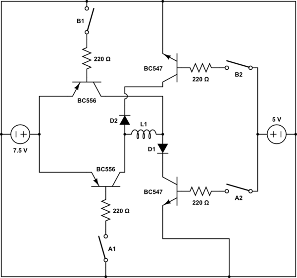
When switches A1 and A2 are closed, the dot should flip one way. Closing B1 and B2 should flip the dot back again.
I've built the circuit on a breadboard, replacing the 4 switches with 4 pins on a microcontroller.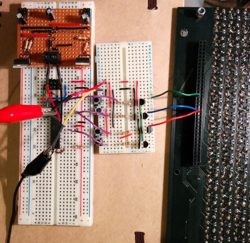
Code
const uint8_t columnVcc = 1 << PORTD7;
const uint8_t columnGnd = 1 << PORTD4;
const uint8_t rowVcc = 1 << PORTD5;
const uint8_t rowGnd = 1 << PORTD6;

void resetPins()
{
    PORTD = rowVcc | columnVcc;
}

void on()
{
    PORTD |= rowGnd;
    PORTD &= ~columnVcc;
    _delay_ms(1);
    resetPins();
}

void off()
{
    PORTD |= columnGnd;
    PORTD &= ~rowVcc;
    _delay_ms(1);
    resetPins();
}

int main(void)
{
    DDRD = 0xFF;
    resetPins();
    off();
    _delay_ms(250);

    while(1)
    {
        on();
        _delay_ms(50);
        off();
        _delay_ms(50);
    }
}
By default, all of the general purpose input/output pins are high impedance. This means they are essentially disconnected from the circuit. The positive lines to each side of the coil go through a PNP transistor, which require a low base to turn on. Taking the base high should turn them off. Likewise the negative lines to each side of the coil go through an NPN transistor which requires a low base to turn them off. The resetPins function takes care of this.
Next Step
I'm going to make things a little less boring than a single dot. That is all.