Flipping Back to Basics - Current Situation
25 March 2014I'm eager to get a microcontroller hooked up to these dots now that I know how to address individual pixels. The microcontrollers I have to hand are ATmega48PA's and they have 23 input/output pins. To control all 240 dots I need to be able to control 46 wires so as it stands I could only control 7 columns of 8 rows, as a row takes up 2 wires.
Fortunately I have a couple of 8-bit shift registers, these take 3 connections as input and offer up to 8 as ouput. They are serial in parallel out (SIPO) and can be daisy-chained, meaning that the same 3 connections can control any multiple of 8 outputs. Having 2 of these means I get an extra 16 outputs by sacrificing 3, allowing me to control a total of 20 columns of 8 rows. That's two thirds of the display so I'm happy with that for a first attempt.
These microcontrollers are delicate things so I want to be sure I'm not going to break them. I made a reading of the current across the coil of a single dot to be 53mA. The datasheet for the ATmega48PA says it can only handle 40mA on any pin though.
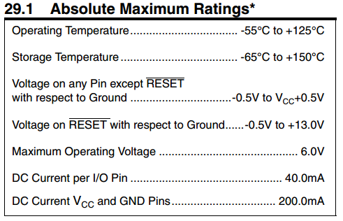
Bad times. Fortunately Ohm's Law states that I = V/R, that is, current is equal to voltage divided by resistance. This can be rearranged to R = V/I, meaning that if I know the desired current and voltage I can work out what resistance I need in total. The current is 0.04A, voltage will be 4.5v, so 4.5/0.04 = 112.5, meaning I need a total resistance of 112.5Ω. The multimeter tells me the resistance of the coil by itself is 83.6Ω, 112.5 - 83.6 = 28.9, the closest resistor I have is 27Ω so I'll measure some values using that in series with the coil to see what current is drawn.
It only draws 41mA, which is great, I'm happy to risk that tiny bit extra with the microcontroller. Unfortunately at that current it doesn't activate the dot and perform any flipping action.
That would explain what these boys are doing on the connecting PCB that I've not yet looked at much.
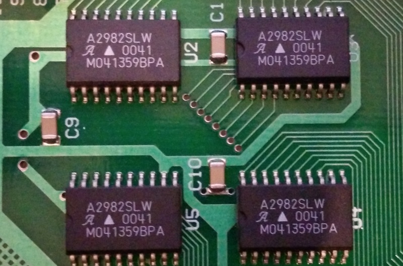 These are 8-channel source drivers. They allow 8 low-current inputs to drive 8 high-current outputs. 4 of them make 32 high-current outputs which is just enough for the 30 columns.
Next Step
I'm not going to be able to control the dots without the extra components on the adjoining PCB. I'm going to have to follow the same process again with that in order to work out how to control that which will in turn control the display dots.