Flipping Back to Basics - Multiplexing
24 March 2014Last time I deconstructed the dots to find out how they work, and was able to flip a single dot back and forth by applying a voltage across 2 connectors. Now I'd like to know how 240 dots, with 4 connections each, are controlled from just 60 wires.
Tracing
I'm ignoring the existence of the LEDs for the time being and focussing on the flipping side of things. Using the multimeter to check for continuity I'm able to construct the following trace of connections up on the rear of the display panel PCB. I'm not fantastic at editing images so please bear with me throughout this.
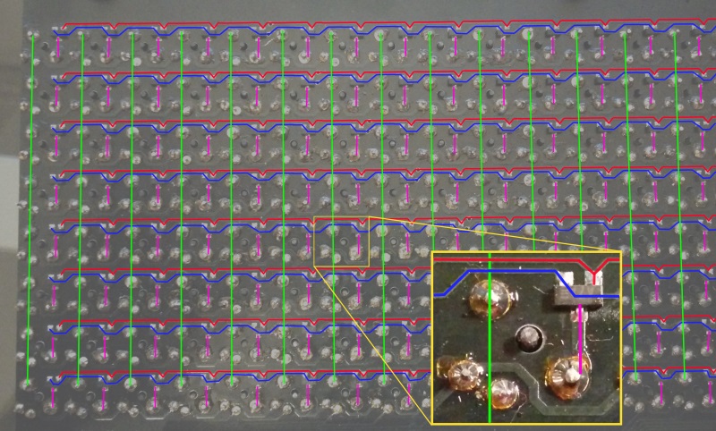
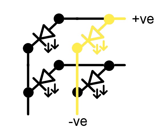
Columns are made up of one end of the electropermanent magnet coil. Rows are made up of the other end of the coil. The rows are passing through a tiny IC, visible in the zoomed box, and whilst I have no idea what this is all about just yet, this still looks to me like multiplexing. I've seen examples of multiplexing LEDs before and it's a fairly basic concept. All the anodes in a row are connected together, and all the cathodes in a column are connected together. This enables the addressing of individual LEDs by applying a positive voltage to the desired row, and grounding the desired column. This leaves just a single route for the current to flow, like so:
This multiplexing has 2 wires per LED, one positive and the other negative. The traced connections on the display, however, reveals 3 wires per coil. I need to dig in to multiplexing a bit further to see if I can make sense of this.
Multiplexing
One of the reasons multiplexing works is that LEDs only let current flow in one direction. If this was done with bulbs instead of LEDs then all of them would be illuminated since the current could freely travel through the connected circuit. The coils that control the flipping in this circuit will let current flow in either direction so without some further magic there would be no way to address one by itself. This suggests to me that the little IC is perhaps some sort of diode, but diodes have only 2 leads, one anode and one cathode. Multimeter to the rescue again with its diode tester.
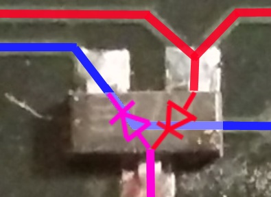
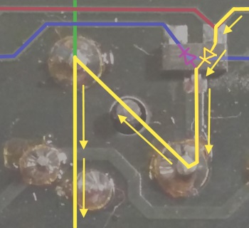
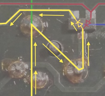
The little IC houses 2 diodes arranged as in the above amendment to the original trace. This is becoming clearer now. The double connections to each row are to allow the multiplexing to take place with current flowing in either direction. When we want to turn a dot on we apply a positive voltage to the rows red wire and connect the columns green wire to ground. To turn the dot back off we apply a positive voltage to the columns green wire and connect the rows blue wire to ground. I've (tried to) illustrate this below.
The designers of this board could easily have given the columns 2 wires and a diode and had the row use only 1 wire, but there's a good reason for how it's done. With 30 column wires plus 16 (2 8 rows) row wires, there is a total of 46 connections required in order to address every single dot individually. If we turn it round and calculate the alternative, we get 8 row wires plus 60 (2 30 columns) column wires giving a total of 68 connections required. Clearly the former, with fewer required connections, is more efficient.
Next step
Now that the mechanics of addressing individual dots are known I want to construct a simple circuit connected to this board and turn some dots on and off using a microcontroller. This should be a bit of fun and give some nice visible results.