Flipping Back to Basics - Deconstruction
23 March 2014Last time I was able to work out the make-up of a message to the display over RS-485, there are still many unknowns in the protocol though. The main one that concerns me is the apparent reset of all the dots after 50 seconds. The next logical step, therefore, is to discern what the different control characters are used for.
Software is logical, I am not.
My overall goal is to control arbitrary dots, rather than just send text messages, so I'm going to dive into the other end of this now and focus on the display hardware. By understanding what flipping a dot entails I hope to be able to control them without the use of the RS-485 interface. I'll be working backwards, starting with the visible parts and tracing them back through the circuitry.
Deconstruction
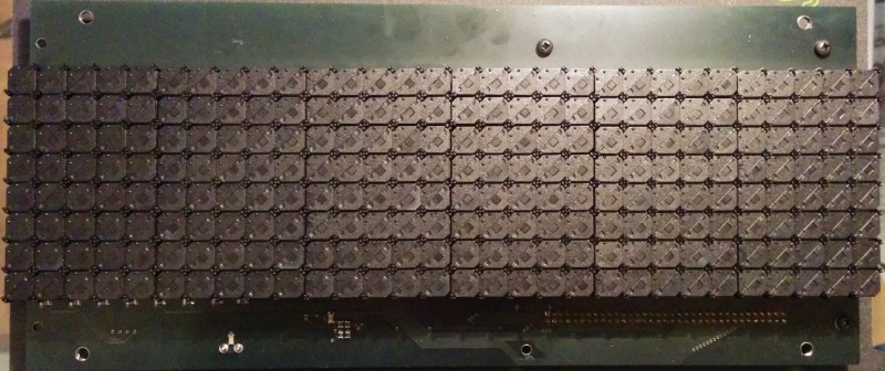
The 90x8 display I used last time is the victim, it doesn't put up much of a fight as I fiddle with its nuts and cables. Inside it's made up of the main control board which has the RS-485 and power connectors. Connected to this board, by a single 60 ribbon cable with multiple connectors, are 3 panels containing the dots. I'll take one of these panels out to inspect further.
The Dots
The dots are the visible portion of the panel and are very simple things. Each dot is a black plastic square with one half painted a nice fluorescent yellow. On the fluorescent half there is a small hole in the corner to allow light to shine through from the LED underneath.
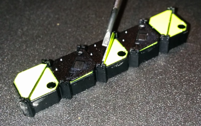
There's then a small piece of plastic, half the size of the square, pivoted about the centre. One side is painted fluorescent yellow such that when flipped correctly the entire dot appears either yellow or black. The key to their functionality is a small permanent magnet near the pivot point, this enables it to be flipped using magnetic force very easily.
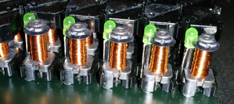
The plastic dots clip on to these little things. Each one of those is a coil of wire wrapped around a magnetic core creating an electropermanent magnet. Electropermanent magnets work by using the coil to change the polarity of the magnetic core. This means that the magnet will continue attracting or repelling after power is cut and so current only needs to flow through it for a very short period of time.
Next to each coil is the LED that shines through the hole in the plastic dot.
Flipping Out
Turning this display panel over allows us to see the connections for both the electropermanent magnet and the LED. I've highlighted them on the diagram that follows.
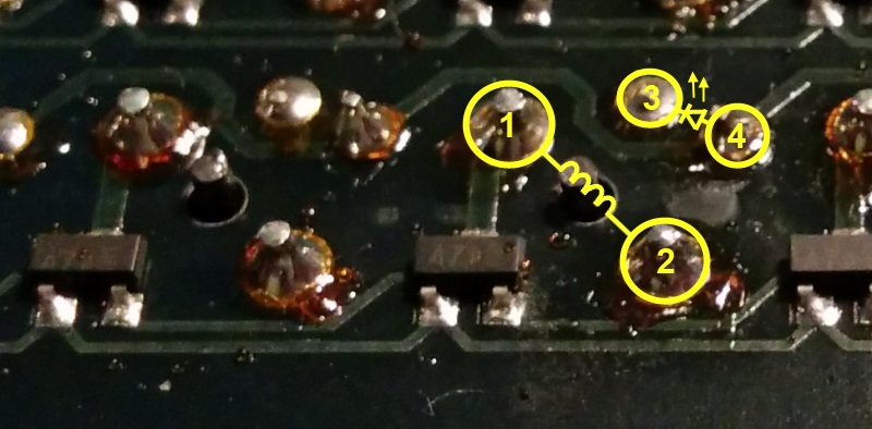 The electropermanent magnet is connected at 1 and 2, the LED is at 3 and 4
I want to find out how much voltage needs to be applied for the dot to flip but I don't want to damage anything by using too much. I've got a variable transformer with 1.5v intervals so I can start out low and move up until I get it to flip.
We get some flips at 4.5v. The dot flips to show the yellow side when the current flow is from 2 to 1, and back to black when the current flows in the opposite direction, from 1 to 2. I measure the current draw for a single coil at 4.5v to be 53mA.
Next Step
The next step I want to take is tracing the circuit connections backwards from the dot to see some of the techniques used to control 240 dots, with 4 connections each, from just 60 wires in the ribbon cable.